

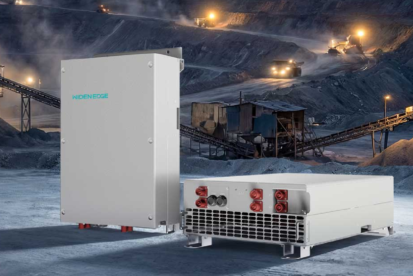
Problem statement: why a 600 kW inverter often becomes the bottleneck
High short-term swings from solar and wind push a storage inverter into roles it was not always specified for: grid stabiliser, fast reserve and smooth ramping agent. When a microgrid controller must arbitrate between rooftop PV, gensets and storage, the inverter’s thermal headroom, response speed and control modes determine whether the system holds frequency and voltage or trips into protection. During commissioning of a bess controller at a commercial microgrid in Mombasa I watched an otherwise well-sized array lose value because the inverter could not sustain sustained 30–40% ramp events without derating.
Core technical problems to solve
Several repeatable failure modes appear when planning a 600 kW inverter for variable renewables:• thermal overload during sustained charging/discharging spikes;
• poor dynamic response to sudden PV drop (cloud transients);
• inadequate fault ride-through or anti-islanding settings that clash with the wider protection scheme;
• weak coordination with the site-level energy management system, causing conflicting set-points;
• unclear power-to-energy (P:E) mismatch—an inverter sized for 600 kW without matching storage hours leads to unhelpful state-of-charge profiles.
Sizing and specification choices that matter
Make specific decisions, not vague allowances. Important checks:• Define the use case: peak shaving, firming, black start or a mix. That sets acceptable continuous vs peak duty for the inverter.
• Allow headroom: specify short-term overload capability and ensure cooling is sized for repeated cycling.
• Match P:E ratio to mission: a 600 kW inverter paired with less than 1 MWh will force rapid cycles; pair it with battery capacity and chemistry chosen for the duty.
• Ask for grid-forming capability if the inverter must support islanding; otherwise specify fast grid-following response and clear handover rules with the microgrid controller.
Control architecture and commissioning priorities
Control is the decisive discipline. A precise coordination plan prevents oscillation between generation assets and avoids SOC collapse. Set these priorities in commissioning:• Clear hierarchy: which controller issues the final active and reactive set-points? Lock that in and verify at low risk.
• Rate-limit profiles: limit charge/discharge ramps to what the battery and inverter can sustain thermally, not just what they can deliver momentarily.
• Fault and protection alignment: harmonise anti-islanding, over/under frequency and voltage trip curves across inverter, genset and protection relays.
• Test scenarios: run stepped PV loss, full-load transfer and frequency disturbance simulations live with the BESS control logic engaged.
Operational best practices that reduce downtime
Operators save time by doing these practical routines:• Daily SOC envelope monitoring — flag repeated deep cycles before they shorten battery life.
• Scheduled firmware and parameter checks after any grid code update.
• A short library of verified set-points for common conditions: high solar, storm cloud passage, planned maintenance.
• Log-driven alarms tuned to headroom thresholds rather than absolute values; that prevents nuisance trips during normal variability.
Common mistakes and how to avoid them
Teams keep repeating the same errors. Avoid:• assuming the inverter can mimic the battery indefinitely — match thermal and electrochemical limits;
• leaving open-loop handoffs between inverter and microgrid controller; always require a deterministic authority;
• under-testing edge cases such as simultaneous high PV and sudden load drop; those reveal inverter control limits;
• ignoring manufacturer guidance for sustained power delivery—get the continuous vs peak curves in writing.
Checklist for procurement and technical acceptance
Use this concise acceptance checklist before sign-off:• verified continuous and overload ratings with thermal curves;
• documented control modes and their priority against the microgrid controller;
• completed dynamic tests (PV ramp down, black start, fault ride-through);
• battery capacity and chemistry matched to expected duty cycle;
• commissioning report that shows stable handover of control under at least three stress scenarios.
Final synthesis and practical value
If you treat the 600 kW inverter as a component in a control system rather than as a single-piece specification, the project delivers stable power and predictable battery life. Practical engineering — clear authority lines, realistic thermal margins, matched P:E ratios and tested handover sequences — prevents surprises when renewables swing quickly. Those concrete choices explain why field teams working with partners such as WidenEdge find fewer reworks and smoother operations.