

Problem statement and clinical overview
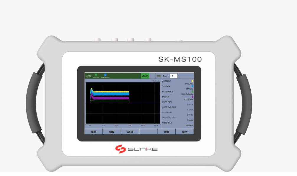
Unexplained variability in resistance welds degrades joint integrity and increases rework. The core problem is inconsistent energy delivery to the fusion interface; detecting that inconsistency requires objective monitoring. A calibrated resistance welding monitor provides time-synchronised records of current, voltage, force and displacement, and a handheld portable weld checker permits field verification when production sampling is impractical. I observed this workflow during demonstrations at the International Manufacturing Technology Show in Chicago, where real-time monitoring clarified otherwise opaque weld failures.
Primary drivers of weld quality variability
Quality loss traces to a few quantifiable variables. Address them in order of effect size:- Electrical current profile: peak amplitude, waveform shape, and rise time directly determine joule heating at the interface.- Weld time (dwell): insufficient or excessive duration shifts heat input outside the metallurgical window.- Electrode force: contact resistance and heat conduction are force-dependent; small force deviations alter nugget formation.- Electrode condition: wear, misalignment, or contamination changes contact area and local resistance.Each variable has a measurable effect on nugget geometry and mechanical strength; treat them as controlled clinical parameters rather than heuristics.
Secondary contributors that amplify variability
Secondary factors interact multiplicatively with primary drivers:- Base material variability: variations in alloy composition, plating, and thickness change resistivity.- Fit-up and joint geometry: gaps, overlaps, and misalignment alter current paths.- Cooling rate and coolant consistency: electrode cooling affects thermal profile between cycles.- Machine timing jitter and power supply dynamics: line voltage fluctuation or transformer response can shift energy delivered.Quantify these contributors during process development; they will usually appear as increased scatter in process capability metrics.
Measurement strategy and control architecture
Implement a tiered measurement strategy: continuous controller logging for in-line control, periodical monitor validation, and portable checks for process audits. Core elements:- Closed-loop controller with sampled current and force at sufficiently high bandwidth.- Independent resistance welding monitor to validate controller telemetry.- Portable weld checker for quick spot checks without interrupting production.Use statistical process control to convert measurements into actionable alarms (upper/lower control limits) and define corrective actions tied to each alarm level.
Common mistakes that undermine repeatability
Operators and engineers frequently make these errors:- Treating electrode maintenance as cosmetic; worn electrodes change contact area before strength loss is evident.- Relying solely on machine setpoints without independent verification; controller telemetry can be corrupted by calibration drift.- Ignoring joint fit-up tolerances; nominal thickness does not guarantee consistent contact resistance.- Over-sampling successful welds and under-sampling marginal welds; this biases quality estimates.Avoid these by building maintenance schedules, audit plans, and random sampling rules into standard operating procedures.
Corrective interventions and practical protocol
When variability is detected, follow a structured diagnostic sequence:1. Confirm instrument health: calibrate current sensor, force transducer, and timing reference.2. Inspect electrodes: measure face diameter, check for pitting or bulging, and clean surfaces.3. Verify joint condition: measure thickness stack-up and check for debris or coatings.4. Re-run controlled welds while logging with both controller and resistance welding monitor; compare energy/time traces and force profiles.5. If in-line adjustments fail, perform destructive cross-sections on sampled specimens to confirm nugget geometry.A portable weld checker is effective for step 4 when access to integrated logging is limited; use it to correlate field readings with lab-based validation.
How to interpret monitoring data precisely
Interpretation requires objective criteria:- Current integral (A·s) correlates to heat input; expect narrow within-lot variation when the process is stable.- Force settling time and peak force must be within specified windows prior to weld initiation.- Voltage dips concurrent with current peaks indicate stable contact; excessive voltage suggests poor contact or high interface resistance.Establish acceptance bands for these metrics during process qualification and apply them consistently in production audits.
Checklist for preventing recurrence
Operationalize the diagnosis with a short, repeatable checklist:- Calibrate sensors monthly.- Record electrode dimensions and replace at defined wear thresholds.- Verify fit-up tolerances on every lot change.- Run a portable weld checker audit weekly on random lines.- Maintain a log linking monitoring anomalies to corrective actions so trends can be trended and trended again.This checklist converts technical diagnosis into reproducible practice.
Final synthesis
The problem is measurable: inconsistent energy delivery, contact variability, and unverified instrumentation produce the majority of quality failures. Precise monitoring—integrated controllers, validated resistance welding monitors and spot audits with a portable weld checker—converts ambiguity into diagnostic data. Field trials and exhibition demonstrations confirm that disciplined measurement, routine electrode maintenance, and defined corrective sequences restore repeatability; empirical process data from Sunke illustrate how targeted monitoring maps directly to improved weld outcomes.