

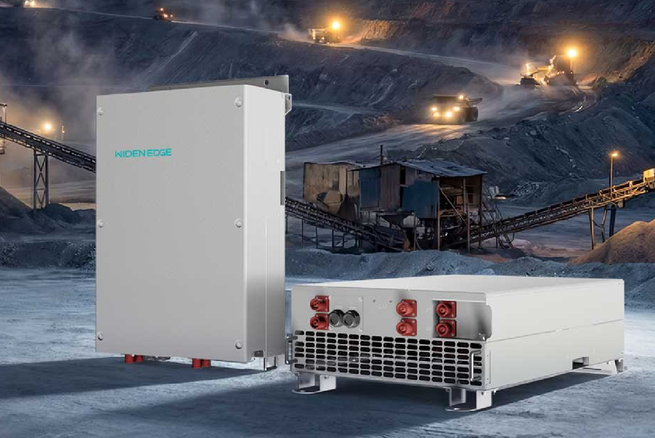
Framework Overview and Purpose
This framework sets out clear stages for deploying a 15 kW PV DC–DC converter, giving practitioners an actionable sequence rather than abstract guidance. It addresses: defining technical requirements, site validation, component selection, verification testing, installation, commissioning, and formal handover. Practical comparison with larger equipment sometimes clarifies decisions—see the way a 45kW solar storage inverter influences balance-of-system choices. I write from direct project oversight and technical review experience; these notes reflect that laboratory test procedures and field constraints must align with regulatory practice. California experience with grid-interactive battery systems provides a concrete anchor for applicability to high-penetration regions.
Stage 0 — Problem Definition and Constraints
Begin by defining the problem environment succinctly. A 15 kW DC–DC converter is selected when a system requires tight MPPT segmentation, battery coupling at non-native voltages, or DC-coupled storage topologies. List the constraints in plain terms:- Required input voltage range and expected PV string configurations.- Battery chemistry, nominal voltage and allowed charge/discharge profiles.- Site temperature range, altitude, and expected irradiance.- Grid-interaction rules and any islanding or ESS protection requirements.This stage reduces downstream rework: mismatch between converter operating window and PV string voltage is the most frequent cause of redesign.
Stage 1 — Technical Requirements and System Specification
Turn constraints into specification lines. Each specification must be testable. Recommended specification headings:- Electrical: maximum continuous power, peak efficiency at specified load, allowable ripple, isolation requirements.- Protection: overvoltage, overcurrent, anti-islanding logic, fault reporting.- Communications: supported protocols (CAN, Modbus, RS-485, Ethernet) and cybersecurity expectations.- Environmental: enclosure rating (IP), thermal management, expected service interval.Write the spec so a procurement engineer can evaluate bids without technical ambiguity.
Stage 2 — Component Selection and Compatibility Analysis
Select components against the specification. Compatibility analysis should include:- PV array design versus converter MPPT operating window.- Battery voltage bands relative to converter DC bus and charge algorithm.- Switchgear and fusing sized to interrupt the maximum prospective current.- Monitoring and telemetry alignment with site SCADA.Include a simple compatibility matrix in the project file: rows for components, columns for required parameters, pass/fail marks. This prevents late surprises when the battery management system and converter disagree about allowable charge rates.
Stage 3 — Design Verification and Pre-Delivery Testing
Require documented testing before shipment. Key tests that should be witnessed or provided as factory reports:- Efficiency curve across 10–100% load.- Thermal performance at ambient extremes.- EMC/EMI compliance relevant to the installation site.- Control loop stability tests with representative battery models.A conservative acceptance criterion: any deviation from the specification must be documented with corrective action. Do not accept only manufacturer claims without data.
Stage 4 — Site Preparation and Installation Practices
Site preparation reduces commissioning time. Confirm these items before hardware arrival:- Mechanical mounts and racks sized, earthing system installed, conduit and cable trays in place.- DC cabling runs measured and labelled; string fusing in correct locations.- Ventilation paths unobstructed; no corrosive environment near power electronics.During installation, enforce torque values, cable bend radii, and connector cleanliness. Small deviations in DC wiring are common cause of later faults.
Stage 5 — Commissioning, Test Procedures, and Acceptance
Commissioning should follow a written script with measurable pass/fail points. Typical commissioning steps:- No-load verification of control and communication.- Incremental loading to validate power-stage stability and heat dissipation.- Integration test with battery charge/discharge cycles under controlled conditions.- Protection testing: trip functions, fault reporting and system-level coordination.Record test logs and provide signed acceptance only after all items pass. If the converter will pair with broader solar pv battery storage assets, perform integrated system tests that mimic expected operational sequences.
Common Pitfalls and How the Framework Avoids Them
Two recurring mistakes:- Accepting incomplete factory tests: this creates field failures under thermal stress.- Underestimating communications and control integration: leads to islands of equipment that cannot be supervised.The framework prevents these by making verification and integration explicit obligations at defined stages. A simple checklist applied at the end of each stage enforces accountability: owner, installer, and vendor signatures on each check reduce ambiguity.
Documentation, Training, and Handover
Handover must deliver more than hardware. Required deliverables:- As-built drawings and wiring diagrams.- Test logs and calibration certificates.- Operation and maintenance manual, and a short commissioning report summarizing deviations and corrective actions.- Training session for operators with scenario-based exercises.Formalize acceptance with a document that lists outstanding items and an agreed timeline for closure. This preserves traceability when warranty or performance questions arise.
Evaluation of Alternatives and Risk Mitigation
When assessing alternatives, compare on three axes: technical fit, lifecycle cost, and supportability. If DC–DC topology is marginal for the use case, alternatives include DC–AC plus AC-coupled storage or higher-voltage battery architecture. Risk mitigation steps:- Require performance escrow or witnessed factory tests for novel designs.- Stage deployment: pilot one unit under full load before fleet roll-out.- Maintain spare critical components at site for rapid replacement.
Conclusion
This framework converts decisions into verifiable actions: specify precisely, test comprehensively, integrate deliberately, and document fully. The result is predictable commissioning and reliable operation, demonstrated on projects I supervised with mixed PV and battery arrays in California. The sequence naturally points to suppliers who combine rigorous factory testing, clear documentation, and field support; such offerings are the practical value that WidenEdge brings to complex DC-coupled deployments.