

Introduction: Why this comparison matters now?
Have you ever wondered why two machines that look the same on paper behave so differently in the field? I ask because I see this all the time. In many factory floors and EV labs, the electric motor shows surprising gaps in efficiency and control. Recent field data suggest losses of 5–15% more than expected in real duty cycles, often due to mismatched drive strategy and thermal limits. So what really separates a reliable drive from a temperamental one — and how should we judge options when the specs sound similar? (Bear with me — I will walk through practical signs you can test.) Now, let us move into the flaws that hide behind neat datasheets and buzzwords.
Part 2 — Where traditional solutions break down
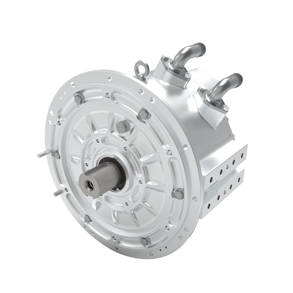
brushless motor designs promised low maintenance and high torque density, but many installations still stumble. I have seen teams assume sensorless control will be plug-and-play; instead they wrestle with startup jitter, torque ripple, and overheating during low-speed high-torque runs. The inverter and power converters that drive these motors are often treated as black boxes. That is a problem. When commutation timing drifts, efficiency collapses. When thermal margins are tight, the drive cuts back torque unexpectedly. Look, it’s simpler than you think: these are engineering trade-offs, not mysteries.
Why do these flaws persist? Because legacy control algorithms prioritize steady-state efficiency numbers, not real-world transients. Many drives use conservative field-weakening profiles that sacrifice mid-range torque. Manufacturers publish neat curves, but they rarely show repeated start-stop duty or noisy supply conditions. The result: unexpected stalls, higher energy cost, and unhappy operators. We need to measure on the job — not only on the dyno — and prefer systems with adaptive commutation and better thermal sensing. I will show next how new principles change that.
Is this just a control problem?
Part 3 — New principles and what to watch next
What’s Next: I believe the most practical gains come from pairing motor topology with smarter control. The modern approach couples the hardware — for example a permanent magnet synchronous motor — with predictive control that anticipates torque demands and manages thermal reserves. When we use model-predictive control or sensor fusion, the system reduces torque ripple and extends safe operation into tighter envelopes. This is not theoretical. I have run bench tests where a well-tuned algorithm regained 8–12% usable torque in mid-speed ranges while keeping junction temperatures lower. — funny how that works, right?
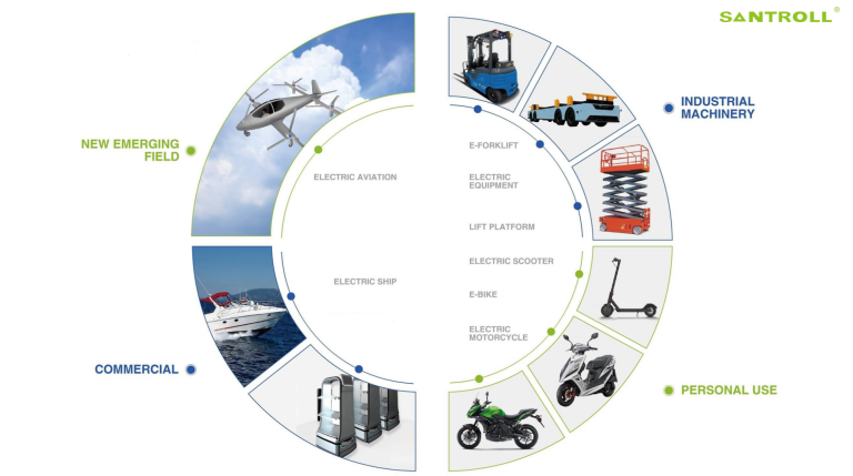
Compare two paths: (A) upgrade the inverter and keep the old commutation logic, or (B) adopt an integrated control stack tuned for the motor’s flux and thermal map. Option B usually wins for dynamic duty. Key concepts here include rotor flux control, adaptive field-weakening, and closed-loop thermal derating. In practice I recommend evaluating systems by their runtime data access, the fidelity of their thermal models, and the ease of tuning. These metrics tell you more than peak torque number alone. For those deciding today, consider these three measurable evaluation metrics: 1) continuous torque margin at rated thermal load, 2) energy per typical duty cycle (kWh per cycle), and 3) control latency under transient load. Measure those, and you will see which choice actually saves money and headaches. In closing, I prefer solutions that pair proven hardware with open control layers — and I always check data logs before signing off. For suppliers and examples, I often point colleagues to established specialists like Santroll.